Precision, Speed, and Control: The Hydraulic Servo Valve Is Being Reengineered
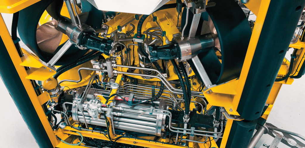
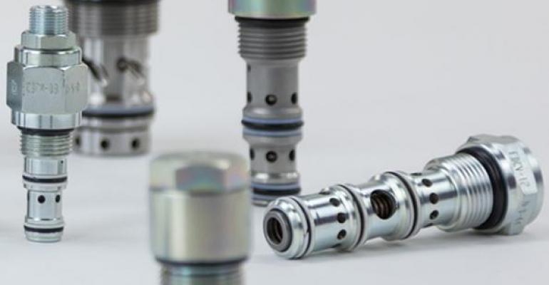
Hydraulic systems are undergoing a significant shift—not in principle, but in execution. One of the clearest signs is what’s happening with servo valve technology. Precision control, high-pressure operation, and smart integration are no longer seen as separate goals. Thanks to recent developments in design and manufacturing, they’re being combined into