As developing nations look to increase their infrastructure capabilities and realise the full potential of their natural and human resources, manual labour is giving way to automated and motorised equipment that does work at a quicker pace with better results. Today efficiency isn’t measured by cubic feet of material moved per liter of petrol consumed, rather by cubic feet per minute. And with the large number of infrastructure projects planned, a quintessential need is for better roads for their connectivity.
Even as new cities sprout upand the old ones swell in size, there is a tremendous need for efficient and regular maintenance and upkeep of inter-city vehicular highways and intra-city thoroughfares. Road laying equipment is getting more advanced with the advent of proportional hydraulic technology with better and more exact control of operations with minimum human intervention and error.
One of the interesting concepts is in a road milling machine. This has a large rotating roller equipped with hard metal cutters which mills off the surface, usually at an angle. Milling, or cold planning, is one of those tools that serve a variety of purposes. Milling is often used to remove surface distresses, maintain or correct elevation, restore roadway geometric properties such as cross-slope, and improve surface characteristics. Milling provides a supply of reclaimed asphalt pavement (RAP) that can be recycled into the new surface and generally improves the bond between layers as well.
In the case of these machines up until in the recent past, the milling depth and the angle were set with the help of push buttons by the operator (Up, Down, Left Raise/Lower and Right Raise/Lower) and continually corrected with the visual feedback he received either by observing the operation himself or by being guided by a secondary operator standing outside. This required a high level of concentration from the operator and frequently led to mistakes in the setting which invariably resulted in a less than ideal situation.

A new solution was implemented where the controlling activity is to be automated with the milling depth and milling angle to be predefined and set and complied with by means of a control system operating on a feedback loop.
Physical Structure
The roller is controlled via two cylinders that either move together to raise or lower it, or independently to vary the milling angle. The cylinders would be controlled via spool valves that are actuated through a PCB that gets its inputs from the operator. Since there is no feedback, the spool valves would usually be of the conventional type.
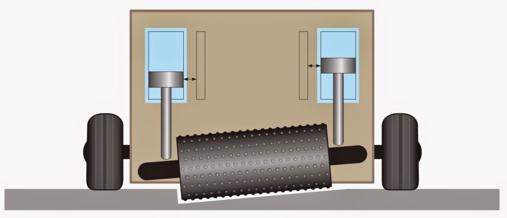
Schematic for the Physical Structure of the Hydraulic System
Solution Approach
With regards to the roller, the two hydraulic cylinders which set the required milling depth would remain untouched. Replacing the conventional spool valves with Proportional Controlled valve, the oil flow to the cylinder would be metered. This is measured with position control systems that provide feedback to the control electronics. Every axis has its own position control circuit which automatically complies with the predefined milling depth. An offset signal is supplied to the two position control circuits, by which the milling angle can be set.
The variable for the “Milling Depth” is provided with the help of a potentiometer at the “Analogue Input 1” and is the command variable to both position control circuits as an analogue value in the form of a voltage. On the controller card, this is used as the command value for Cylinder 1 and Cylinder 2.
The variable for the “Milling Angle” is also provided with the help of a potentiometer but at the “Analogue Input 2” and is the analogue command value in the form of a voltage. The controller card adds this to the position command variable for Cylinder 1 and subtracts this from the position command variable for Cylinder 2. Thanks to the flexible parameterisation possibilities, the MD2 digital amplifier enables the addition / subtraction of the two command values (milling depth / milling angle).
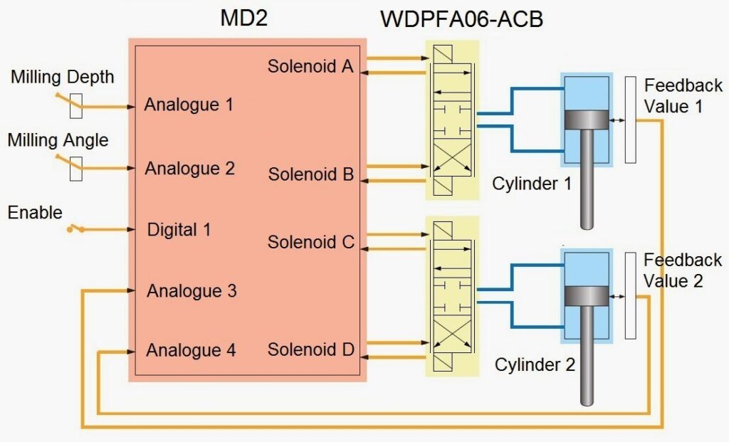
Proportional Control Layout Showing Feedback Loop
The position of the two cylinders is provided at “Analogue Input 3” and “Analogue Input 4” as an analogue value in the form of a voltage supplied by the two position control measuring systems “Feedback value 1” and “Feedback value 2”. The predefined position of the cylinders is complied with automatically by the control system and corrected in case of any deviation.
With the MD2 amplifier module, two channels are used internally. Both channels are operated in the controller mode “Axis Position Controlled”. Channel 1 controls Cylinder 1 through the solenoids A and B while Channel 2 controls Cylinder 2 through the solenoids C and D.
In case of both channels, the value of “Analogue Input 1” is used as the Command value 1 but the value of “Analogue Input 2” as command value 2 is used as-is for Channel 1 and inverted for Channel 2.
Customer benefit

The proportional system brings in a new dimension to the equipment and is easily plugged in to the existing framework of the machine. Road Milling is of course only one of the many uses for this particular layout which finds a place in any system requiring tandem as well as independent cylinder control with feedback looping. In conclusion, the benefits of proportional technology in construction equipment are varied and far reaching with
- Automated, economical working sequences
- Low effort for the implementation
- Solution from a single hand
One Response
Great article! I really appreciate the clear and detailed insights you’ve provided on this topic. It’s always refreshing to read content that breaks things down so well, making it easy for readers to grasp even complex ideas. I also found the practical tips you’ve shared to be very helpful. Looking forward to more informative posts like this! Keep up the good work!